Task Lighting for Kitchens with Open Shelves or No Upper Cabinets
Recommended Task-Lighting Plan for Open Shelves and Kitchens Without Upper Cabinets
If an open shelf already sits above the worktop, start with the Lumaz Through-Wood Touch Sensor COB LED Strip Light Kit beneath the shelf and position the light toward the working edge. If the wall is bare, first create a slim wall-mounted carrier that projects the light forward and shields it from view; if the kitchen is being remodeled, integrate a channel and low-voltage wiring into the millwork. The correct route is determined by support geometry and cable concealment—not by the absence of a cabinet alone.
Use the existing architecture when
- A floating shelf has a stable underside above the prep, sink, or appliance zone.
- A wall rail or shallow ledge can carry a down-facing light without appearing bulky.
- New millwork can conceal the strip, channel, low-voltage cable, and service access.
Change the route when
- The only possible mounting position leaves the LEDs visible at normal standing or seated sightlines.
- A cable must cross an open wall, window, range area, or frequently cleaned backsplash.
- The shelf is decorative, unstable, too shallow to shield the source, or not positioned over the real task zone.
Lumaz planning principle: every route needs three lines to agree: the task line on the counter, the source line where the light sits, and the service line used by its cable, adapter, driver, or charging routine. A visually clean installation fails if any one of those lines is ignored.
Choose One of Three Buildable Lighting Routes
Begin with the object that can physically carry and hide the light. The counter may look similar in all three kitchens, but the support, concealment, and maintenance path are different.
| Available architecture | Buildable lighting route | Source and coverage | Wire strategy | Main trade-off |
|---|---|---|---|---|
| Existing open shelf above the task surface | Under-shelf linear light | Run beneath the shelf and toward its front half so light reaches the working edge rather than washing only the wall. | Exit at a shelf end, pass through a planned rear route, or keep a removable charging path accessible. | The source can become visible from across the room if the shelf is thin or mounted high. |
| Bare wall with no shelf or upper cabinet | Wall-mounted carrier with a down-facing light | Use a shallow rail, ledge, or shielded profile that brings the source forward and aims it down over the active counter. | Conceal low-voltage cable behind or within the carrier; otherwise accept one deliberate vertical cable route rather than several loose crossings. | The carrier becomes part of the wall composition and must be designed, not treated as an invisible cabinet substitute. |
| New backsplash, side panel, niche, hood surround, or custom millwork | Integrated channel and concealed low-voltage system | Recess or shield a continuous strip so the finished detail controls view, reflection, and spill. | Plan the driver, dimmer, cable path, and access point before the finish surfaces close. | This gives the cleanest result but requires coordination and is the least reversible route. |
If the counter zones themselves are still undefined, complete the Kitchen Counter and Work-Zone Lighting Plan first. That page determines which parts of the counter deserve task light; this page determines what can carry that light when conventional wall cabinets are absent.
Mark the Task, Source, and Service Lines Before Buying
Line 1 · Task
Trace the surface that must remain visible
Place the cutting board, coffee machine, dish rack, or other real object on the counter. Mark the working width and depth rather than the full wall length.
Line 2 · Source
Find a horizontal face that can aim light down
Use a shelf underside, a wall-mounted carrier, or an integrated recess. A light fixed flat to a vertical wall is not automatically a task light; its orientation and shielding must direct useful light onto the counter.
Line 3 · Service
Draw the complete power and maintenance path
Show the outlet, adapter or driver, controller, cable entry, and accessible service point. For rechargeable lights, show how the fixture will be removed and where it will charge.
- Stand at the task position and look toward every likely source location. Reject a location that puts the bright source directly in the normal sightline.
- Hold a temporary light or neutral mock-up at the proposed source line. Confirm that the beam reaches the front working edge without leaving the backsplash as the brightest surface.
- View the installation from the adjoining room, dining seat, and kitchen entry. A source hidden while working may still be exposed from farther away.
- Draw the service line before choosing fixture length. One clean cable exit is usually easier to integrate than several short fixtures with separate visible leads.
Build the Route That Matches the Kitchen
Route 1 · Existing open shelf
Turn the Shelf Underside into a Continuous Task-Light Plane
Recommended setup: run one smooth linear source beneath each shelf section that overlaps a real task zone. Start toward the shelf's front half, then move inward only enough to hide the light from the room. Keep the cable exit at a shelf end or planned rear path instead of letting it drop through the middle of the composition.
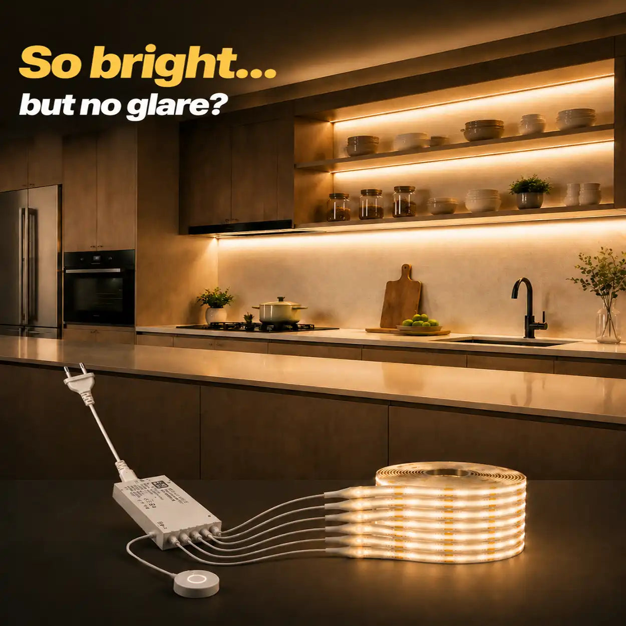
- Best fit: a stable wood shelf above a regularly used counter, with continuous power and a route for the centralized adapter and strip leads.
- Fit facts: 1m, 2m, 3m, and 5m lengths; 2-, 4-, 5-, and 6-strip options; 8mm PCB; cuttable every 2.5cm.
- Why this model: the 320 LEDs/m COB line avoids a dotted appearance beneath an exposed shelf, while stepless dimming lets the same shelf support active prep and quieter evening use.
- Not ideal when: the shelf cannot conceal the source or cable, the installation must be removable, or no outlet can serve the run.
- Measure only the shelf length above the active task zone; do not light an entire decorative shelf by default.
- Mock up both a front and a more recessed source position, then inspect the counter and the cross-room sightline.
- Choose one end for the cable exit and keep the adapter accessible rather than sealing it into the shelf or wall.
- Install the strip only after checking shelf material, finish adhesion, heat exposure, and the manufacturer's instructions.
Route 2 · Bare wall
Add a Slim Wall Carrier That Aims the Light Down
Recommended setup: use a shallow wall rail, ledge, or shielded profile as the architectural carrier, then attach a slim down-facing bar beneath it. Align the carrier with the task zone rather than the room center, and design one intentional cable descent or a concealed low-voltage route. Do not mount a linear bar flat against the vertical wall and assume it will light the counter correctly.
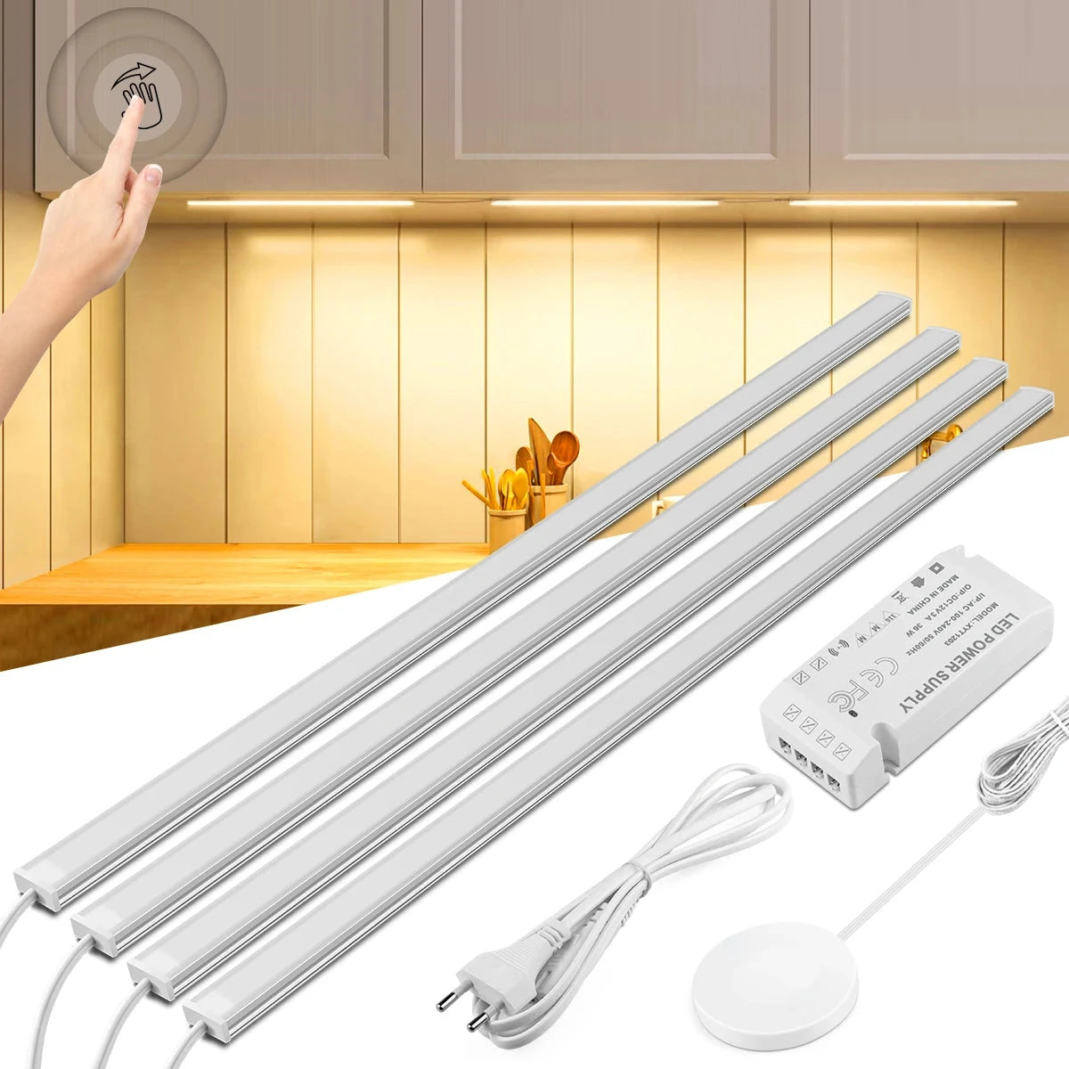
- Best fit: a defined coffee, prep, or landing zone where a purpose-built wall carrier can support and visually shield a straight powered bar.
- Fit facts: 30cm, 40cm, and 50cm bars; 1- to 6-light kits; 7mm aluminum body; warm or cool white; hand-sweep and stepless touch-dimmer control.
- Why this model: the thin straight body is easier to integrate beneath a shallow carrier than a bulky fixture, while the available kit sizes support one or several coordinated task zones.
- Not ideal when: the bar would remain visible from across the room, the wall carrier cannot project light over the work surface, or a custom curved or irregular route is required.
Wall-route boundary: the Lumaz light bar is the light source, not the structural wall carrier. Select and fasten the carrier for the wall construction and expected load, preserve access to the light and wiring, and use appropriate installation help where concealed power or wall modification is involved.
Route 3 · Remodel or new millwork
Integrate a Shielded COB Line into the Finished Detail
Recommended setup: coordinate a recessed or shielded channel with the backsplash, shelf edge, hood surround, side panel, or custom niche before finishes are installed. Place the luminous line forward enough to reach the task surface, use the finished lip or diffuser to block direct view, and keep the low-voltage power equipment accessible.
- Best fit: a planned remodel or custom joinery detail where the strip, channel, cable, driver, and control can be specified as one serviceable system.
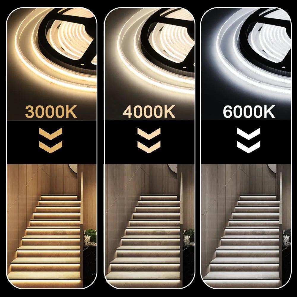
- Strip facts: DC12V, 320 LEDs/m, CRI above 90, 3000K/4000K/6000K choices, IP30 or IP68 versions, 1m–20m lengths, cuttable and dimmable.
- Why this model: the high-density COB source supports a continuous luminous line, while the flexible 2-pin strip can follow a custom straight or shaped millwork detail.
- Not ideal when: a ready-to-use kit is required—the strip does not include a power supply or dimmer—or the finished construction cannot preserve access to its power components.
- Draw the channel, shielding lip, cable exit, driver location, and service opening on the millwork or backsplash elevation.
- Choose the indoor or protected strip version according to the actual environment; do not use a product rating to excuse poor placement near heat, steam, or splash.
- Coordinate a compatible power supply, dimmer, channel, and connectors for the selected strip and run length.
- Test the complete low-voltage system and sightlines before the access panel, trim, or finished surface is closed.
Resolve Glare and Visible Wires as Part of the Architecture
| Observed problem | What it usually means | Change before final installation |
|---|---|---|
| The LEDs are visible from the dining area or kitchen entry. | The source is too close to the front edge, the shelf/carrier is too thin, or there is no shielding lip. | Move the source slightly inward, add a compatible channel or shield, or redesign the carrier while confirming that the task surface still receives light. |
| The backsplash is bright but the cutting board is dull. | The source sits too close to the wall or points mainly backward. | Bring the source forward or adjust the carrier/channel orientation so light crosses the active counter depth. |
| A glossy counter shows a sharp bright line. | The source is reflected into a normal viewing position. | Mock up a different front-to-back position, improve shielding or diffusion, and dim only after the geometry has been corrected. |
| Several short cables remain visible on an open wall. | Fixtures were selected before one service route was planned. | Group compatible fixtures around one deliberate cable path, integrate the route into a wall carrier, or change to a rechargeable route for a small isolated zone. |
| The installation looks clean but cannot be repaired. | The adapter, driver, controller, or connectors were sealed behind finish surfaces. | Create accessible service space before closing the shelf, panel, niche, or wall detail. |
After task coverage is solved, use Layered Kitchen Lighting: Balance Task, Ambient and Decorative Light to decide how the open shelf or integrated line should relate to ceiling lights, pendants, and evening scenes. Do not weaken task visibility merely to make every layer equally dim.
Verify the Route Before Fixing It Permanently
- Test the real task. Stand at the prep, sink, coffee, or landing zone with the normal objects in place. Confirm that hands and tools remain visible when the body blocks the ceiling light.
- Check the working edge. Make sure the front part of the counter receives useful light instead of leaving the brightest area on the wall.
- Check two sightline heights. Inspect the source while standing at the counter and while seated or entering from the adjacent room.
- Return reflective surfaces. Replace glossy appliances, polished accessories, and normal backsplash items before accepting the source position.
- Operate and service the system. Reach the control naturally, follow the entire cable path, and confirm that the adapter, driver, connectors, or rechargeable fixture can still be accessed.
Installation boundary: keep adapters, drivers, connectors, and ordinary indoor wiring away from heat, steam, and splash exposure. Concealed line-voltage work, new outlets, wall penetrations, and custom low-voltage system design should follow product instructions and applicable local requirements, with qualified installation help where needed.
Questions That Determine Your Lighting Setup
Can an open shelf replace an upper cabinet as the lighting support?
Yes, when the shelf is stable, overlaps the real task zone, has enough underside area to carry and shield the source, and offers a workable power route. Use the Lumaz COB kit for a smooth powered line; choose another route when the shelf is decorative, too shallow, or unrelated to the active counter.
Can I mount a light bar directly on the vertical wall?
Only if its mounting and orientation actually direct light down onto the work surface and prevent direct glare. In most bare-wall layouts, a shallow carrier or shielded profile is the more controllable route. Mount the Lumaz 7mm bar beneath that horizontal carrier rather than treating a flat wall position as equivalent to a cabinet underside.
What if I cannot hide any cable on the open wall?
For one small, isolated task zone, use a removable Lumaz rechargeable bar and plan an accessible charging routine. For a long daily-use counter, redesign the wall carrier or integrate a serviceable low-voltage path; multiple exposed charging lights usually create more visual and maintenance clutter.
Should the light be hidden even if that moves it close to the backsplash?
No. The source must still reach the working edge. First test a position that lights the task surface, then use a shelf lip, carrier, channel, or diffuser to control visibility. If concealment forces the light too far back, change the architectural detail instead of accepting a bright wall and dark counter.
Continue with the Right Lumaz Path
Collection hub
Compare Lumaz Under Cabinet Lighting
Use the collection after choosing the shelf, wall-carrier, or integrated route to compare current strip and light-bar sizes, power types, colors, and controls.
Next decision · Work zones
Map the Kitchen Counter and Work Zones
Continue here when the mounting route is possible but the prep, sink, cooking, coffee, and landing zones still need different coverage priorities.
Next decision · Lighting layers
Balance Task, Ambient and Decorative Light
Use this guide after task coverage is established and the next decision is how the open shelf or integrated line should relate to the rest of the room.