
DIY Wiring Guide: Transformer Selection, Wire Gauge, and Circuit Planning for Multiple Puck Lights
Table of Contents
- How low-voltage puck lights work
- Calculate power and current: watts, amps, and required VA
- Choose the right transformer/driver: types, dimming, and compatibility
- Wire gauge and voltage drop: calculation method and practical table
- Planning circuits and layout for multiple puck lights
- Wiring methods, connections, and practical installation tips
- Tools, testing, and commissioning checklist
- Safety, code considerations, and common pitfalls
- Frequently asked questions (FAQ)
- Conclusion
How low-voltage puck lights work
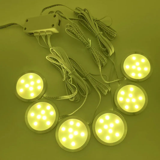
Low-voltage puck lights are typically 12V or 24V LED fixtures powered by a transformer (also called a driver). They run in constant-voltage circuits and are wired in parallel to maintain consistent brightness.
Calculate power and current: watts, amps, and required VA
Use watts and volts to determine current (I = P/V) and transformer VA (V × A); always add a safety margin of 20–30% to the calculated load.
Steps and rules of thumb:
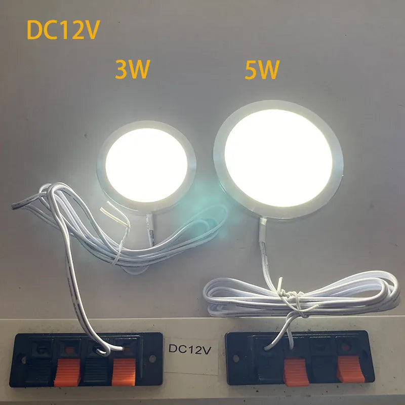
- Find each puck's wattage (manufacturer spec). If unknown, measure or use a typical range: 1–4 W for modern LED puck lights.
- Total watts = number of pucks × wattage per puck.
- Total amps = total watts ÷ driver voltage (12 or 24 V).
- Required transformer VA ≈ total watts × 1.25 (25% buffer) to allow headroom and avoid overloading electronic drivers.
Example: Ten 2 W pucks at 12 V → total = 20 W → current = 20 W ÷ 12 V = 1.67 A → choose a 12 V, 30 VA driver (12 V × 2.5 A = 30 VA) to be safe.
💡 Get it right the first time! Lumaz LED puck lights deliver maximum brightness with minimal, energy-efficient power draw.
Choose the right transformer/driver: types, dimming, and compatibility
Select a transformer that matches voltage, load type, dimming needs, and installation location (inside cabinet, closet, etc.).
Transformer/driver types
- Magnetic (iron-core) transformers — older tech, heavier, accept low loads but can hum and are large.
- Electronic (switch-mode) drivers — lighter, efficient, more common for LED pucks. They often require a minimum load and can be sensitive to triac dimmers.
- Constant current drivers — used for certain LEDs; most puck lights use constant-voltage drivers (12/24 V), not constant current.
Dimming and control
- Make sure the driver is dimmer-compatible. Electronic drivers may require an LED-rated dimmer (PWM, trailing-edge or leading-edge as specified).
- For remote or smart controls, choose drivers with built-in dimming interfaces (0–10V, DMX, or PWM) or pair with a compatible dimmer/controller.
Practical selection checklist
- Confirm puck voltage (12 V vs 24 V).
- Calculate total wattage and add 25% headroom.
- Pick a driver rated for that VA and for the environment (dry, damp, or wet location).
- Verify dimming compatibility or choose non-dimming if uncertain.
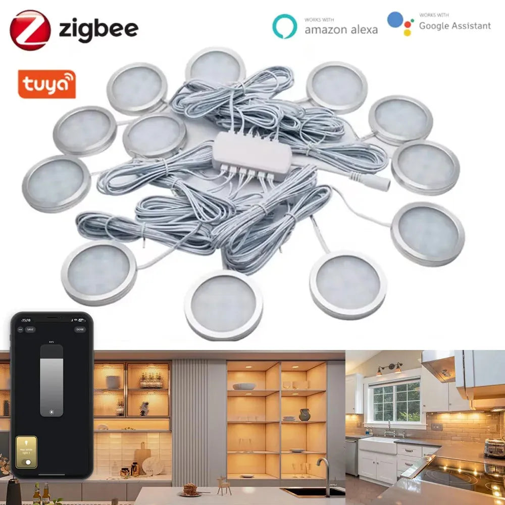
For users who want to skip the complexities of choosing transformers, wire gauge, and compatibility, an all-in-one solution can simplify the process. Tuya Zigbee Smart Under Cabinet LED Puck Lights (12V, full kit) includes everything needed—drivers, connectors, and smart controls—so you can focus on placement and lighting effects without worrying about technical calculations.
Wire gauge and voltage drop: calculation method and practical table
Voltage drop matters more at low voltages; choose wire size based on current and run length to keep drop ≤3% for good brightness and longevity.
Formula (round trip): Vdrop = I × R × L, where R is conductor ohms/ft and L is one-way distance × 2 (round trip). Aim for Vdrop ≤ 3% of supply voltage (0.36 V for 12 V).
| AWG | Ω/ft (approx) | Max one-way length for 3% drop @ 2 A (ft) | Max one-way length for 3% drop @ 5 A (ft) |
|---|---|---|---|
| 18 | 0.00639 | 28 | 11 |
| 16 | 0.00402 | 45 | 18 |
| 14 | 0.00253 | 71 | 29 |
| 12 | 0.00159 | 113 | 45 |
| 10 | 0.00100 | 180 | 72 |
Notes:
- Table assumes 12 V system and targets ≤3% voltage drop (0.36 V).
- For 24 V systems, voltage drop effect halves; you can double allowable lengths for the same percent drop.
- If your run exceeds these lengths, choose thicker wire (lower AWG) or use multiple feed points/parallel runs.
Planning circuits and layout for multiple puck lights
Good planning reduces voltage drop, simplifies installation, and keeps the system code-compliant. Start with a wiring diagram and a parts list.
Design steps (quick planning checklist)
- Determine puck spacing and measure cable lengths from driver to farthest puck.
- Decide voltage: use 24 V for long runs or many fixtures, 12 V for short runs and retrofit jobs.
- Select driver size with 25% buffer and choose wire gauge using the table above or a calculator.
- Plan feed topology: single daisy chain, multiple radial feeds, or multiple zones (recommended for >12 fixtures).
- Note switch/dimmer location and include junction boxes accessible per local code.
Topologies explained
- Daisy chain (single run) — simplest: puck-to-puck. Best for short runs and few fixtures.
- Home-run (radial) — separate cable from driver to each puck. Minimizes voltage drop and isolates failures.
- Multiple zones — group pucks on separate drivers or outputs; ideal for dimming scenes or long kitchens.
Recommendation: For more than eight pucks or runs over 25 feet, consider a 24 V system or split into two circuits to avoid voltage drop and ensure uniform brightness.
Wiring methods, connections, and practical installation tips
Use secure connections, proper polarity, and accessible junctions. Maintain consistent wiring practices to avoid failures.
Common connection types
- Push-fit connectors (male/female quick connectors) — convenient but check amp rating.
- Solder + heat-shrink — permanent, reliable, but less serviceable.
- Wire nuts or Wago lever nuts — secure and easy to service; use low-voltage rated models.
Best practices
- Keep polarity consistent (positive to positive, negative to negative). Mark the + conductor.
- Group pucks into logical runs; keep junction boxes accessible and label them.
- Seal any connections in cabinets from high heat and moisture — use silicone gaskets or rated enclosures.
- When in doubt, run larger gauge wire than calculated — the labor cost is small compared to rewiring later.
🔧 "I wired my under-cabinet pucks in two zones with a 24 V driver. Brightness stayed even all the way across and dimming worked perfectly." — DIYer in a home-improvement community
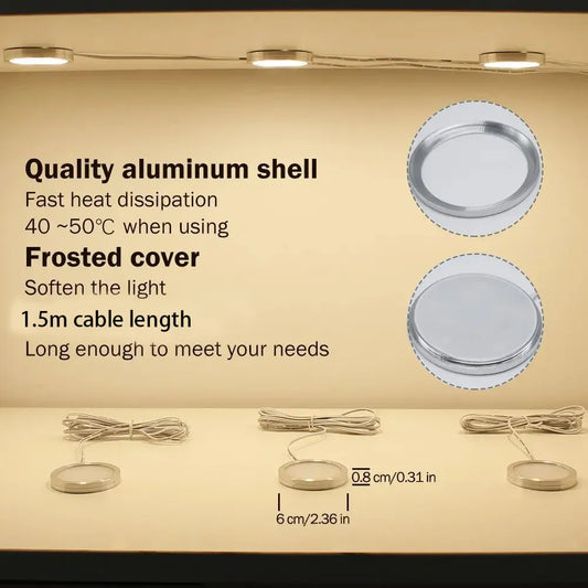
For users seeking a straightforward installation with minimal wiring hassle, compact fixtures can simplify placement in tight spaces. 12V ultra-thin aluminum LED puck lights are ideal for mini ceilings, cabinets, and RVs, offering easy connections and reliable performance while keeping wiring neat and unobtrusive.
Tools, testing, and commissioning checklist
Test voltage, polarity, and dimming function before final installation. Use the right tools and follow a commissioning sequence.
Essential tools
- Multimeter (true RMS preferred)
- Wire strippers, crimpers, and screwdrivers
- Wire cutters, heat shrink, soldering iron (optional)
- Label maker or tape and marker
- Voltage tester / non-contact detector
Commissioning steps (order)
- Verify driver output voltage with no load.
- Connect one puck; confirm correct polarity and that it lights as expected.
- Add pucks incrementally and measure voltage at the far end to confirm acceptable drop.
- Test dimmer through entire range; check for flicker or buzzing.
- Secure all connectors and document the circuit layout for future service.
Safety, code considerations, and common pitfalls
Follow electrical safety best practices and local code. Low-voltage systems still connect to mains via the driver and must meet installation rules.
Key safety points
- Turn power off at the breaker before working on mains wiring feeding the driver.
- Install drivers/transformers in ventilated, accessible locations per manufacturer instructions.
- Protect low-voltage wiring from physical damage and keep it separate from line-voltage wiring where required.
Citations and further guidance:
- For safe work practices and electrical hazards, consult OSHA's electrical safety resources: https://www.osha.gov/electrical.
- For lighting efficiency and LED considerations, see the U.S. Department of Energy guidance on LED lighting: https://www.energy.gov/energysaver/led-lighting.
Common mistakes to avoid
- Undersizing the driver—never operate a driver at or above 100% of its rating.
- Ignoring voltage drop—visible dimming or color shift indicates poor design.
- Using incompatible dimmers—check driver-dimmer compatibility to avoid flicker or failure.
- Poor connections—use properly rated connectors and test every joint.
Frequently asked questions (FAQ)
Can I mix different wattage puck lights on the same driver?
Yes, if they share the same voltage and the total wattage stays below the driver's rating with a 25% buffer. Mixing can produce uneven brightness unless the varied wattages are intentional for layered lighting.
Is 12 V or 24 V better for kitchen under-cabinet pucks?
24 V is better for longer runs and higher fixture counts because voltage drop is proportionally smaller. For short runs and a few lights, 12 V is fine and often cheaper.
How many puck lights can I run on one transformer?
Divide the transformer's VA by each puck's wattage converted to VA (for resistive LED loads VA ≈ W). Keep total <= 80% of rated VA to maintain margin. Example: a 60 VA driver can safely supply ~48 W of LED load (allowing 20% headroom).
Do I need an electrician for this project?
If you feel comfortable working with a screwdriver and a multimeter and the job only involves low-voltage wiring and a code-compliant driver installation, many DIYers can complete it. Hire a licensed electrician for mains wiring, changes to branch circuits, or if local code requires it.
Why do LED pucks hum or flicker when dimmed?
Humming and flicker commonly come from mismatched dimmers and drivers or from drivers operating near their minimum load. Use LED-compatible dimmers specified by the driver manufacturer and ensure the load meets the dimmer/driver minimums.
Conclusion
Proper wiring and planning are key to a safe, efficient low-voltage puck light installation. By selecting the right transformer, calculating wire gauge and voltage drop, and carefully planning circuits, users can ensure consistent brightness, reliable dimming, and long-lasting performance while avoiding common pitfalls and safety issues.
Further Reading
Explore the full guide for this topic: How to Install Puck Lights: Placement, Wiring, and Layout Guide
Related Articles
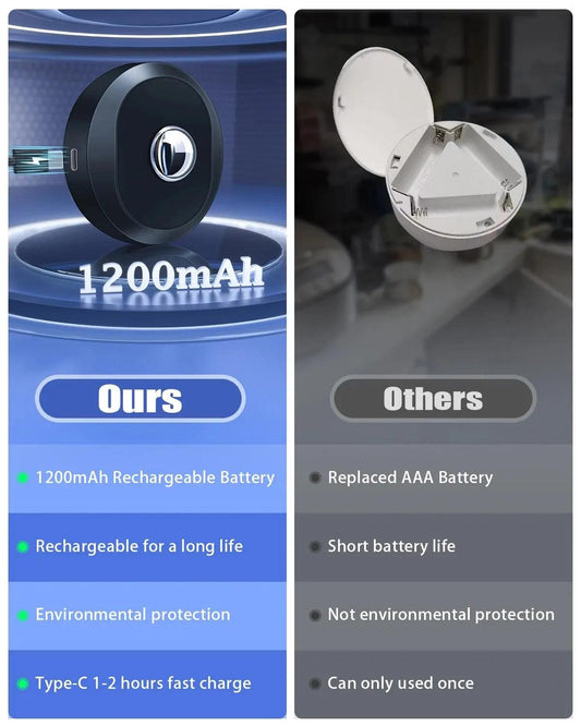
- Hardwired vs Plug-In vs Battery Puck Lights: Which Installation Option Is Right?
- Best Places to Install Puck Lights
-
How to Install and Replace Puck Lights on Ceilings and Under Cabinets
- Best Puck Light Layouts for Kitchen Task Lighting
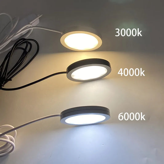
- Puck Light Color Temperature Guide: Kitchens, Closets & Displays


 />
/>
 />
/>
 />
/>
 />
/>
 />
/>