

How to Space Under Cabinet Lighting?
Do Not Use One Spacing Number for Strips, Bars, and Puck Lights
Space under-cabinet lighting by its luminous form: run a continuous strip across each uninterrupted active zone, center modular bars over the work they serve and distribute the leftover edge gaps, and place puck lights on an equal trial pitch with the first and last centers one-half pitch from the zone boundaries. Then test the layout on the real counter before drilling or committing adhesive.
The familiar “8 to 12 inches apart” advice can be a practical mock-up starting range for some puck-light layouts, but it is not a universal specification. Mounting height, beam distribution, output, diffuser, cabinet depth, source position, countertop finish, and the tasks below can all change the final pitch. It is also the wrong calculation for a continuous strip and often the wrong calculation for rigid bars.
Use this rule
- Strip: size luminous length to the active run; solve front-to-back position and segment breaks.
- Bar: add actual module and connector lengths; center the assembled luminous system within the active zone.
- Puck: calculate an equal trial pitch, preserve half-pitch edge coverage, and tighten the pitch if the mock-up shows valleys.
Avoid this shortcut
- Dividing the total cabinet wall length by an arbitrary fixture count.
- Centering every light on a cabinet door while ignoring the work zones below.
- Treating the published beam angle as a hard edge where the light suddenly stops.
Build a Spacing Worksheet for Each Uninterrupted Work Zone
Measure the counter activity first, not the room and not the number of cabinet doors. A hood, window, tall cabinet, corner, depth change, open shelf, or visible cable crossing may divide one wall into separate lighting zones. Complete one worksheet row for every uninterrupted zone.
| Worksheet input | What to record | Why it changes spacing |
|---|---|---|
| Active zone length, L | Start and end points of the counter task, measured along the planned light line | This is the length to cover; unused cabinet underside does not automatically need light. |
| Front-to-back light line | Distance from the cabinet front, plus the lip or valance that hides the source | It changes body shadows, backsplash emphasis, glare, and source visibility. |
| Fixture form | Continuous strip, modular bar, or puck | Each form needs a different spacing method. |
| Real component dimensions | Luminous length, body length, cut interval, connector gap, lead exit, and mounting clearance | Catalog length alone may omit dark joints or installation clearance. |
| Mounting height, H | Vertical distance from the light source to the counter or display plane | A puck's footprint changes with height and optical distribution. |
| Task and surface check | Prep, sink, appliance, display, ambient use; matte, dark, or reflective surface | The same geometric layout can feel uneven or glaring in different conditions. |
Draw the active zone as a line and mark fixed obstructions before selecting products. If fixture type, mounting height, or cabinet construction changes, start a new worksheet row rather than averaging unlike conditions together.
For a Continuous LED Strip, Cover the Zone and Solve the Setback
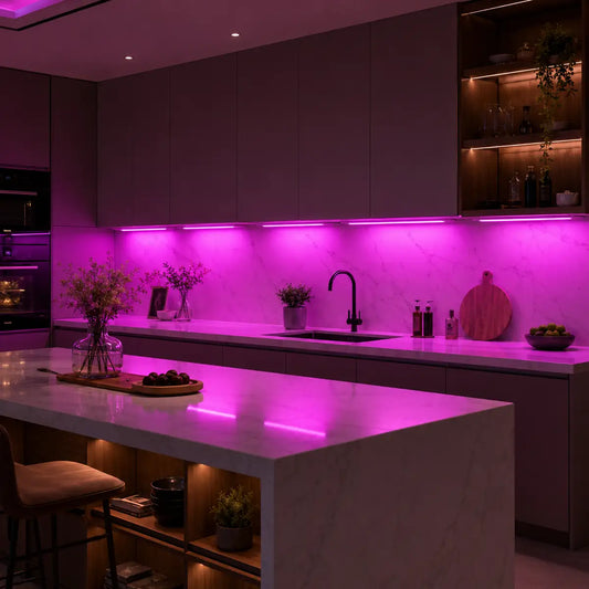
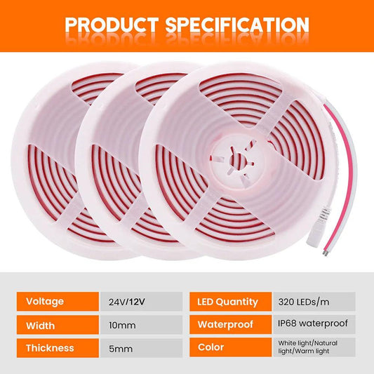
A strip is already a continuous source, so there is normally no center-to-center spacing calculation. Size one luminous segment to each uninterrupted active zone, stop only at an approved cut mark, and account for any non-luminous connector or corner break. Manufacturers distinguish tape that can be cut to varying lengths from rigid fixtures sold in predetermined lengths; that physical difference is why the layout methods should not be combined. See Kichler's cabinet-lighting installation overview.
- Mark the active start and end. Extend coverage to the useful edges of the prep, sink, or appliance zone—not automatically to the cabinet side panels.
- Select a legal cut point. If the strip cannot end exactly at the boundary, keep the short remainder on the less critical edge or choose another strip/cut interval.
- Place the light line front to back. A position nearer the cabinet front commonly helps light the counter in front of the user's hands, but the lip or channel must still shield the source from normal sightlines. Move the mock-up rearward if the source is visible or creates an objectionable reflection.
- Treat every dark joint as a gap. Include corner connectors, solder joints, lead exits, and interruptions in the drawing. Do not label a run “continuous” if a dark connector lands over the main cutting area.
Use a second strip segment when an appliance, window, corner, or cabinet-depth change makes a visible crossover unavoidable. If the primary problem is choosing front versus rear placement rather than run length, use the Under-Cabinet Lighting Decision Guide to resolve source form, concealment, and project constraints before finalizing the spacing worksheet.
For Modular Bars, Add the Real Assembly and Distribute the Remainder
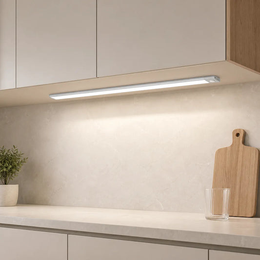
Rigid bars arrive in fixed body lengths. Lay them out as an assembly—bars, dark connector gaps, cable exits, and required clearances—then center that assembly within the active zone. Do not create equal gaps between bare catalog dimensions if the installed connectors occupy additional space.
Use this worksheet calculation:
- Total installed assembly = sum of bar body lengths + fixed connector gaps.
- Remaining edge allowance, R = active zone length L − total installed assembly.
- Centered start and end allowance = R ÷ 2.
| 48-inch worked example | Value | Layout result |
|---|---|---|
| Active zone, L | 48 in | Measured across the counter task, not the cabinet doors |
| Two example bars | 18 in + 18 in | 36 in of fixture body |
| Fixed center connection | 2 in | 38 in total installed assembly |
| Remaining allowance | 48 − 38 = 10 in | Start 5 in from one edge and finish 5 in from the other |
If the remaining edge allowance leaves the active ends visibly dark, do not “fix” it by sliding both bars toward one edge. Choose a longer module combination, add a module if the power system permits, or redefine the active zone. When a sink or primary prep board occupies one side, an intentionally asymmetric assembly is acceptable—but record the task reason so it is not mistaken for a measuring error.
For Puck Lights, Calculate a Trial Pitch and Then Check the Light Between Centers
Puck lights create individual distributions, so the question is whether adjacent pools remain useful between fixture centers. Beam angle helps estimate the spread, but it is not a hard boundary: the Illuminating Engineering Society defines beam angle at the directions where intensity is 50% of maximum. That means the edge of the stated beam is neither darkness nor the same brightness as its center. See the IES definitions of beam angle and luminaire spacing criterion.
When the manufacturer provides a beam angle, use geometry only to estimate the projected beam diameter:
Projected beam diameter D = 2 × mounting height H × tan(beam angle ÷ 2).
Use D as an outer planning envelope, not the final pitch. Output distribution, diffuser, surface response, and the required uniformity still determine how much overlap is useful. When reliable photometry is unavailable, use the familiar 8-to-12-inch range only to build a removable first mock-up.
For an equal-pitch trial layout:
- Choose a provisional pitch, P, from the fixture information and mock-up range.
- Calculate the fixture count as N = round up (active zone length L ÷ provisional pitch P).
- Calculate the actual equal pitch as P = L ÷ N.
- Place the first center at P ÷ 2, then add P for each following center. The final center will also finish one-half pitch from the far edge.
Example: for a 48-inch active zone and a 12-inch provisional pitch, N = 4, the actual pitch remains 12 inches, and the center marks are 6, 18, 30, and 42 inches. Those marks are a test layout, not proof of uniform illumination. Tighten the pitch or change the fixture if the midpoint between pucks remains noticeably dim, while reducing brightness or changing position if the centers form distracting hotspots.
Wide distribution and narrow distribution can serve different outcomes. A puck manufacturer such as Armacost lists products from focused 30-degree optics to broad 120- and 150-degree distributions, reinforcing why puck count cannot be inferred from diameter alone. See its puck-light beam-angle overview.
Use Edge, Gap, Corner, and Task Rules to Correct the First Layout
| Condition | Spacing rule | Reason to revise |
|---|---|---|
| End of an active zone | Strip: reach the useful edge within its cut tolerance. Bar: compare both leftover edge gaps. Puck: begin and end at approximately half the interior pitch. | A full interior-sized gap at the edge creates a visibly under-served end. |
| Cabinet corner | Plan two straight runs unless the selected system explicitly supports the bend or corner connection. | Twisting a strip or improvising a connector can damage the system and rarely produces a clean luminous corner. |
| Hood, window, or tall appliance | End one zone and begin another; do not carry an exposed luminous segment or cable across the break. | The architecture already creates a visual boundary and may require a different power route. |
| Sink, cutting board, or appliance station | Let the task center adjust an otherwise equal layout, then check adjacent coverage. | Uniform cabinet spacing is less important than keeping hands and tools visible where work occurs. |
| Glossy stone, glass, or metal | Keep the physical layout adjustable until source position, diffusion, and dimming are tested from normal viewpoints. | A mathematically even plan can still show repeated bright reflections. |
Equal spacing is a starting geometry, not an obligation to ignore the room. Preserve symmetry where conditions are equal; create a deliberate exception where the task, obstruction, or connection path is different.
Verify Midpoints, Edges, Shadows, and Reflections Before Mounting
Temporary placement is the final spacing calculation. Use removable tape, magnets, or a support that the fixture instructions permit. Restore the cutting board, coffee maker, backsplash objects, and other daily items before judging the light.
- Mark the centers and luminous ends. Also mark every connector, driver, lead exit, and cabinet break.
- View the source from real sightlines. Stand at the counter, doorway, dining seat, and any lower seated position. Adjust the front-to-back line if the fixture or LED image is exposed.
- Check the midpoint between pucks or bars. Move a hand and a matte object across the counter. A repeated bright-dim-bright pattern means the pitch, optics, or source form needs revision.
- Check both ends. Confirm the first and last useful portions of the task zone are not darker merely because the fixtures were centered on cabinet doors.
- Test body shadows. Stand in the working position with the room lighting in its normal state. Move the source line or extend coverage if your hands block the important area.
- Test reflections and dimming. Look across polished counters and backsplashes. Change position, shielding, or brightness before changing fixture count.
- Change one variable at a time. Record the final pitch, edge allowance, and front setback after the acceptable mock-up is found.
Do not copy an absolute phone lux reading into the specification. A phone can help compare relative bright and dim points in the same mock-up, but final performance claims require suitable photometric data or measurement equipment. If a completed installation flickers or dims unevenly rather than showing a geometric spacing problem, use the Flickering, Dead, or Dim Under-Cabinet Lights diagnostic sequence instead of moving fixtures.
Match the Lumaz Product Form to the Spacing Method
Choose the form only after the worksheet identifies the active zone, available length, breaks, power route, and required visual effect. These verified Lumaz options illustrate how product geometry changes the layout; they do not replace the temporary mock-up.
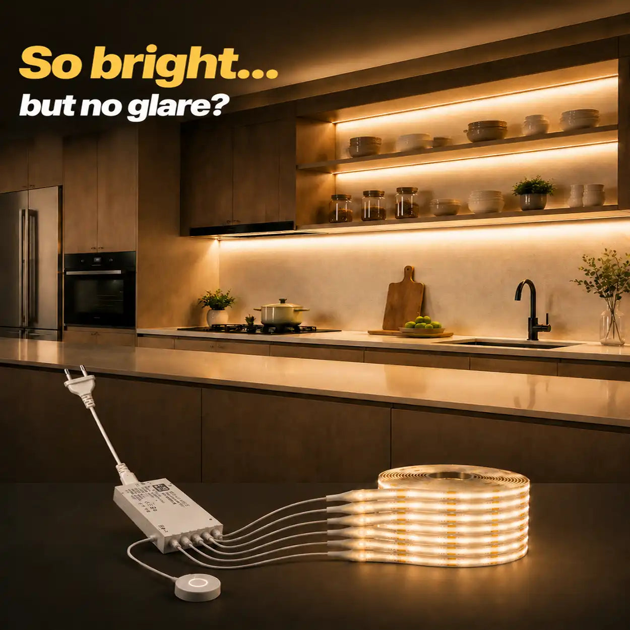
- Plan from: 1m, 2m, 3m, or 5m strip lengths and an approved 2.5cm cut interval.
- Spacing role: cover each uninterrupted active zone as a continuous luminous line instead of calculating fixture centers.
- Check before choosing: the hub, adapter, connecting cable, and through-wood control location must fit the cabinet construction and remain serviceable.
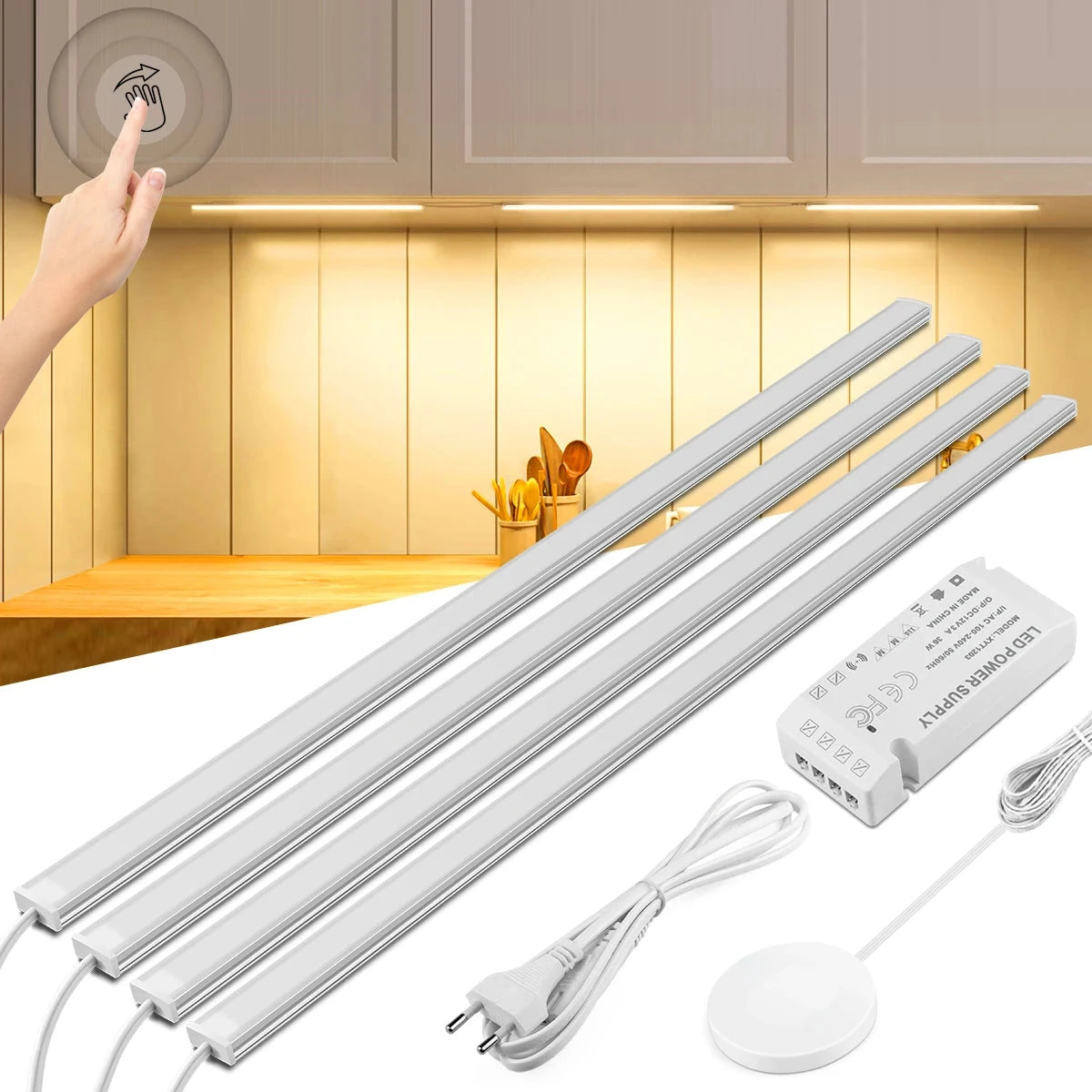
- Plan from: 30cm, 40cm, or 50cm bars and 1- to 6-light kit choices.
- Spacing role: add the chosen bar bodies and real connection gaps, then distribute the remaining allowance across the active-zone edges.
- Check before choosing: the plug, retained clips, hand-sweep control, and interconnection route must suit the planned group.
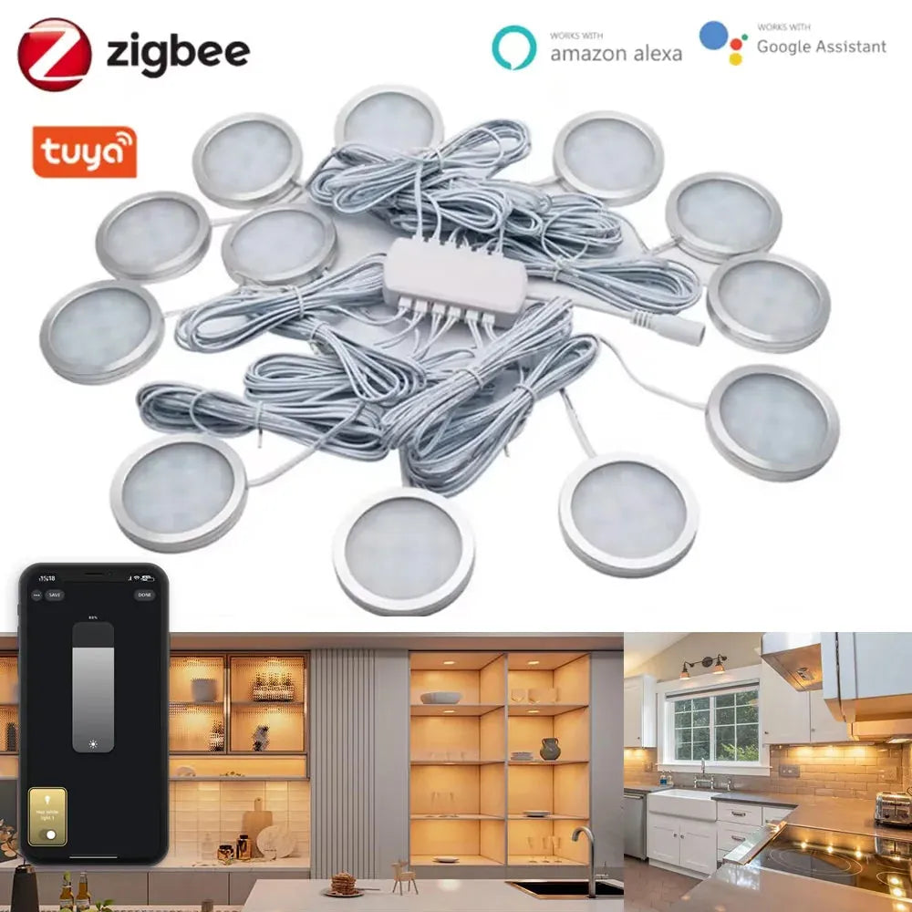
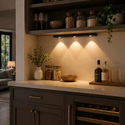
- Plan from: available 2- to 12-puck full-kit quantities and the stated 120-degree beam angle.
- Spacing role: calculate a first equal-pitch layout from the active zone, then verify the light between centers on the real surface.
- Check before choosing: confirm the Zigbee control path, power and cable routing, splitter layout, light color, and required fixture quantity.
If the worksheet points to a different power, control, or fixture form, compare current Lumaz under-cabinet products using the same geometry and mock-up process rather than forcing the room to fit these examples.
Questions That Change Under-Cabinet Light Spacing
How far apart should under-cabinet lights be?
There is no single distance for every source. A strip normally covers the active run continuously; bars are laid out from their actual body and connector lengths; puck lights use an equal trial pitch that is checked for brightness dips between centers. For pucks without reliable photometry, 8 to 12 inches can be a first mock-up range, not a guaranteed final spacing.
How many puck lights do I need for a 48-inch cabinet run?
A 12-inch trial pitch produces four pucks with centers at 6, 18, 30, and 42 inches. That is a geometric starting layout. The final count may change after checking mounting height, the fixture's distribution and output, countertop response, task locations, and the visible light between centers.
Should under-cabinet lights be mounted near the front or back?
Start the mock-up nearer the cabinet front when the goal is countertop task visibility, then confirm the source remains shielded by the cabinet lip or channel. Move or angle it only after checking body shadows, backsplash emphasis, and reflections from standing and seated viewpoints. There is no universal setback that fits every cabinet depth and fixture.
Should puck lights line up with cabinet doors?
Not automatically. Align the layout to the active counter zone and keep the first and last centers near half the interior pitch from its boundaries. Use cabinet doors as reference marks only when their spacing also serves the work below.
Can I mix strips, bars, and puck lights in one kitchen?
Yes, when each form has a different role—for example, a continuous strip over the main prep run and one puck in a display niche. Create a separate worksheet row for each form and avoid mixing overlapping systems over the same task merely to correct a poor first layout.
Should the lights continue around an inside cabinet corner?
Treat the two cabinet legs as separate straight runs unless the selected product explicitly supports the required corner bend or connector. Record the corner's non-luminous gap and view it in the mock-up before fixing either run.
Final layout record: save the active-zone length, fixture form, count or luminous length, center pitch or edge allowances, front setback, connector gaps, control location, and the mock-up change that produced the accepted result. That record is more useful for installation and future replacement than a generic spacing number.














 />
/>
 />
/>
 />
/>
 />
/>
 />
/>